
Home Brew DRO
Duncan Webster and Paul Middlehurst
Why 2 authors?
Easy, I do the metal mangling and act as scribe, Paul does the clever bit, the electronics and software.
Introduction
It all started out when I decided to build a clock. My 5” centre height lathe simply would not grip the 1/8” bar from which I was making spindles. I suppose I could have bought a smaller chuck, but the whole thing seemed out of scale. I then saw an advert for a Cowells lathe at the right price. It actually turned out to be a Perris, and so very old, but still in very good condition, so home it came. Once I had replaced the sewing machine motor with a Parvalux it did the job fine, but the leadscrew and cross slide dials were fixed, and didn’t even have numbers stamped on them. Even if they had, the subdivisions are 0.025mm, which isn’t the handiest for mental arithmetic.
I really couldn’t justify fitting a commercial DRO system, but I managed to buy the cross slide screw assembly off a Pultra (I think) at a very reasonable price in the club auction and grafted it onto the Perris. I resigned myself to having to make a new dial for the feedscrew when Paul found some rotary encoders on the interweb www.vexrobotics.com . At less than £10 each I bought 2 to have a play.
Rotary vs linear encoders
The linear encoders sold by MachineDRO (and others) are attached to the saddle and cross slide and so tell you directly where the tool is, they are not subject to backlash A rotary encoder fastened to the feed screw tells you how much you have turned the handle, but does not account for backlash. However, when using a lathe, you nearly always feed towards the centre with the cross slide and towards the chuck with the leadscrew, so backlash isn’t really a problem. This would not be the case with a milling machine (except for the knee up motion, where gravity does the trick). Typical commercial scales have a resolution of 0.005mm, although they are available with much smaller resolution (at a higher price). As will be explained later, the rotary encoder produces 360 pulses per revolution, and so with my 1mm pitch leadscrew has a resolution of somewhat less than 0.003 mm. I wouldn’t pretend to be able to work to such fine limits, but this shows that the rotary approach has potential. A 3mm pitch leadscrew (~8 tpi) would have ~0.010mm resolution. There is of course no reason why the encoder should not be driven by toothed belt at a higher speed than the leadscrew to get finer resolution, although I’d make up some better bearings.
How a rotary encoder works
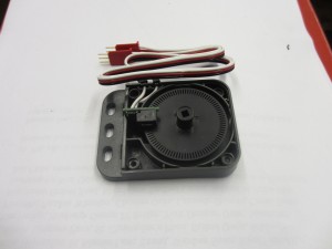
Taking the lid off the encoder reveals a disc with 90 slots, and a sensor incorporating 2 optical switches.
These are arranged so that each sensor produces a square wave output, and the sensors are displaced by ¼ of the distance between the slot centres so that the two outputs are displaced as shown.
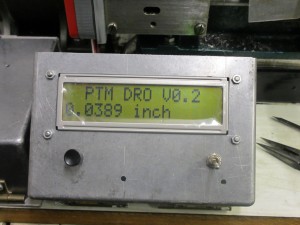
Each change of state (High to Low or Low to High) is called an ‘edge’, so it will be seen that each slot produces 4 edges. This is exactly the same as a linear encoder, but bent into a circle. As long as you maintain the slot width and pitch, you could make our own disc with as many slots as you like (I haven’t actually tried this). The electronics then sorts out which way the disc is turning, and at each pulse adds or subtracts 1 from the current position count. Having previously told the electronics how many pulses represent 1mm (or 1 inch), the count is translated into position and displayed on the Liquid Crystal Diode (LCD).
Mounting the encoder
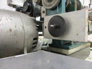
Those of you who have been following Tony Jeffree’s series on adding a clutch to a Cowells (in MEW) will be familiar with the layout of the headstock end of the leadscrew. I made a similar leadscrew extension, but with a fixed collar instead of slotted as I didn’t want to disengage my extension piece.
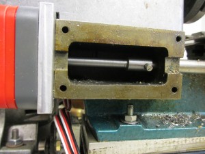
At the left hand end, an alloy plate is bolted to where the banjo adapter should be, with a bush which serves to centralise it in the existing 10mm hole, support the extension and, at the other side, provide a spigot to centralise the housing of the encoder. With the encoder housing centralised on the spigot, holes for the mounting screws were spotted in position and tapped into the alloy plate
The slotted disc has an integral shaft with a 1/8” square hole. As my spigot protruded into the encoder housing, I had to machine a bit off one end. The square drive seemed like overkill to me, I just reduced the end of the leadscrew extension to 1/8” diameter (strong), and clamped the disc axially with an M3 nut. It was a bit of a fiddle to get the axial position right. The slotted wheel mounted on the extension without the rest of the encoder is shown in photo 4.
This is when you remember that the screws which hold the two halves of the encoder housing go in from the back. As it was still ‘under development’, some duct tape engineering provided a temporary solution. I will eventually get round to doing it properly. In retrospect it might have been easier to make up a new bracket to hold the optical sensor, and finally fit a cover over the whole thing, not using the existing housing at all.
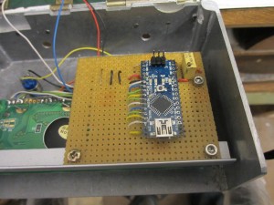
The Electronics
I would have set to and built a bespoke circuit board with a PIC, but Paul introduced the idea of using an Arduino nano. This is a ready made board incorporating the controller and various other necessary bits of magic (around £10 off ebay). Using this massively reduces the soldering, and doesn’t actually cost a lot more than buying the components. Output is displayed on a Liquid Crystal Diode (£2 off ebay for the large digit version, but they can be hard to find, the small digit ones are even cheaper if you buy from Hong Kong). All you need then is a push button for the reset to zero, and we incorporated a toggle switch for metric/imperial select.
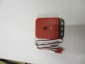
Power supply is from a 5v mobile phone charger, and the die cast box came out of the scrap box (never throw anything away!). The internals and externals are shown in photos 5, 6 and 7. The schematic can be downloaded from our club website (see later)

Other Uses
Subject to the comments on backlash explained above, this setup can be used in a host of applications. One of our club members is looking at incorporating it in his telescope mounting to make finding stars easier (celestial ones, not so called celebrities). The Arduino and LCD can be used with a commercial linear scale, this combination would eliminate the backlash issue. To cater for more axes, just use more units. However whilst you could add a keypad and extra code to get all the functionality of a commercial readout, the cost would then begin to add up, and you might as well buy the commercial set up (see Model Engineers Digital Workshop for alternatives)
Changing the code for different pitch screws
before loading the code onto the Arduino you need to change it to suit your application.
If you have an 8 tpi leadscrew the pitch in mm is:
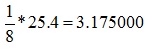
so change the line which states
float Mpitch = 1.000000; //pitch of leadscrew in mm
to
float Mpitch = 3.175000; //pitch of leadscrew in mm
There must be 6 digits after the decimal point, one of the quirks of Arduino.
If you have say 200 slots in your wheel, change the line which states
float Slots = 90; //slots in wheel
to
float Slots = 200; //slots in wheel
Here there must be no decimal point, as Slots is a whole number.
If you are using a linear scale with say 0.005 mm resolution, set Mpitch to 1.000000, and slots to:
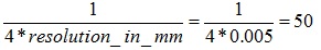
To load this onto your Arduino you would need to install the necessary software (just goggle arduino, it’s free). If this is not your thing, someone in your club will probably be able to help, or you can buy a pre-programmed board from us for £20. Contact via secretary@wdmes.org.uk, telling us how many slots and pitch of leadscrew. All profits to our club. I fear we cannot offer to wire it up for you, or to supply a kit of parts.
Downloads
GNU Free Documentation License
Click diagram to download full size.