
Colour Light Signals
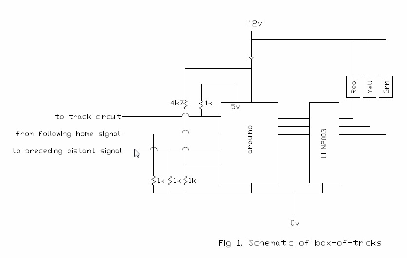
Let me start by saying that this is a joint effort between me and fellow club members Bruce Fairbairn and Paul Middlehurst. Some time ago (ME # Diane will know) I described the semaphore signals we have installed at our track. These works off track circuiting, and are fully automatic in operation. To briefly recap, the track is divided into sections, one rail is connected to ground, and the other rail to the home signal control board. Between the rails is a 1k resistor, and inside the home signal is a second 1 k resistor connected to 5v, all as shown in fig 1. The connection line is thus normally at 2.5v, if a train is in section it falls to 0v, and the control board puts the signal to danger. If the contact is lost the connection line rises to 5v and the control board sets the signal to danger with its lamp flashing. The distant is very similar, but instead of a track circuit, the home signal switches the connection line to ground. The full article is at http://www.wdmes.org.uk/?page_id=1261
After a couple of teething problems, these signals have worked fine, but as they are not weather proof, they have to be installed and taken down each running day. We are now planning to install more signals on our extension, so we have decided that the extra signals will be colour lights which we can leave out all summer, just taking them down for the closed season. This short article describes the trails and tribulations of what initially looked like a simple exercise. It is not meant to be a definitive ‘how to build it’ account, but it might help others to not make the same mistakes. If anyone wants further details contact me via http://www.wdmes.org.uk/
Experience with existing signals
As stated above we had a few teething problems:
Firstly the aluminium wire used to electrically connect the rails is very soft, and seems to relax under the screws securing it to the track, at least the screws come loose over time, and I doubt the screws are stretching. I’ve now tightened them all at least once, and hope that the wire will have work hardened. We haven’t actually lost connectivity, but on the last section to be installed I used stainless steel welding wire, 0.8mm diameter. This is quite springy, so not as easy to get in place, if it proves successful, I’ll make a jig to pre-bend it.
Second issue was my own fault, but it took a long time to find. Between each track section we obviously need to isolate the rail joints. Actually we only need to isolate one side, as there is a common earth, One signal intermittently showed danger when the section in front was unoccupied. Of course every time I took out a test truck it worked perfectly, so it was beginning to be one of those hair tearing issues (and I haven’t got a lot left). Eventually I found that I’d isolated the wrong side, but the very poor contact of aluminium fish plate with aluminium rail meant that most of the time it was isolated anyway, just occasionally it made contact. Moral is, get someone else to check it out, it’s often the case that you don’t spot your own mistakes.
Third issue was short battery life. As explained in the previous article, we do not have mains electricity, and do not want to run the generator just to power signals. The semaphore signals take 220mA each all the time, the red LEDs in colour light signal used to indicate swinging link took 200mA each. The green and yellow took around 100mA each. We also found that the green cluster LED died completely when the battery got down to ~10 volts, but the reds carried on at full brightness, so for those not familiar with the operation it was tempting to assume there was a fault rather than changing the battery. Whilst investigating this, I found that the red LED has a built in voltage converter, and will work down to very low voltages, but as the input voltage goes down the current drawn goes up, I had it at 800mA at one time. It was generally agreed that these LEDs were a lot brighter than needed.
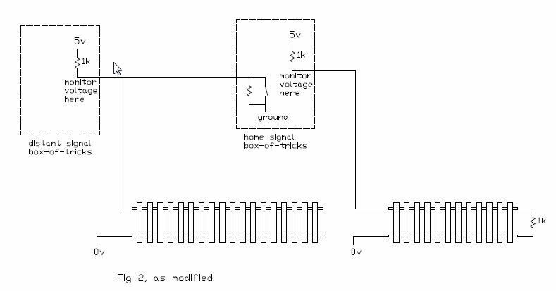
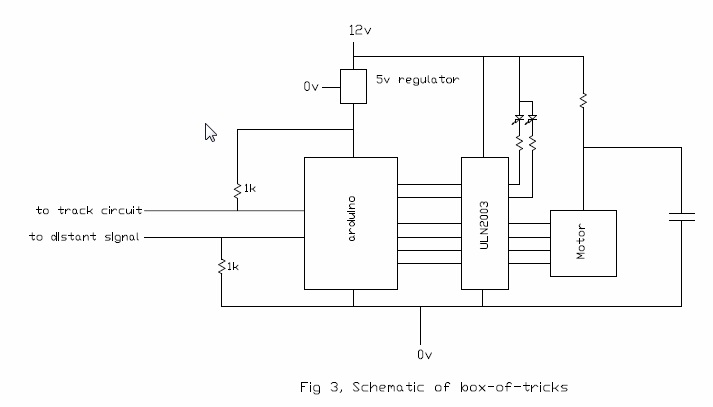
Fourth issue is that as we don’t have continuous track circuit yet, the first distant could be showing clear when there was a train in section. Similarly, when there is a home and distant on the same post, the home could be on danger and the distant on clear. This is not how the big railway did it. The first was solved by track circuiting the section between first distant and first home, and using this circuit to short the connection from home to distant to ground as shown in fig 2. Note there is no resistor across the track here, so loss of connection does not show up. The second will be solved by adding a small circuit board inside the distant signal junction box. The LM311 voltage comparator duplicates the action of the switch inside the home signal, and puts the distant to stop if the home on the same post is at stop, no matter what the home on the next post is doing. See fig 3.
Modifications to swing link signal.
First thing to do was to replace the red LEDs. I couldn’t find any 1 watt MR16 red clusters, so I used 6 off high brightness, 10mm diameter LEDs (ref1) on a piece of stripboard. These are wired up as 2 sets of 3 in series, with a limiting resistor in each leg to limit the current to 20mA, 40mA total at 12.5v input. Owing to voltage lost in the control board (see later) the LEDs only see 11.1v max, 9.1v with flat battery. Due to the forward voltage drop characteristics of LEDs, running at 9.1v reduces the current to ~10mA each leg, but they are plenty bright enough. I’ve also made it so that only one red shows for track occupied, they still flash alternately for swing link open. Current consumption is thus significantly reduced.
To indicate when the battery is getting flat, another of the Arduino inputs has been used to monitor battery voltage. If this drops below 10.5v, when the green LED should be showing it is made to flash on and off. I also fitted a piezo buzzer, but although it seemed loud in my workshop, in the open air it is not easy to hear unless you stand next to the signal, and will not be included in later versions.
Control board
As the board doesn’t have to drive the stepper motor this time, it could all have been done with individual chips, but we’d need quite a few and a host of resistors, zenner diodes etc. It’s all a lot easier with an Arduino, which costs ~£2, less if you buy them in 10s from China. The previous control board was a very good start, but I altered the code quite a bit, not that there was anything wrong with Paul’s code, I just like to do things my own way, then you learn something. The schematic (fig 3) is very similar to the semaphore board. Learning from the swing link, I’ve mounted the board in the back of the box and the LEDs in the front, it looks a lot less like a rabbit’s intestines. Photo 1 shows the prototype, photo 2 shows the production version on a bespoke pcb. It is a fair bit smaller. The (smaller) board layout and code are available from http://www.wdmes.org.uk/?page_id=578.
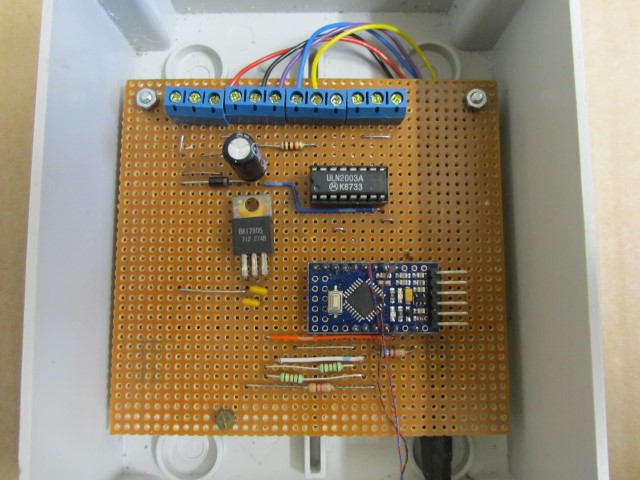
Photo 1
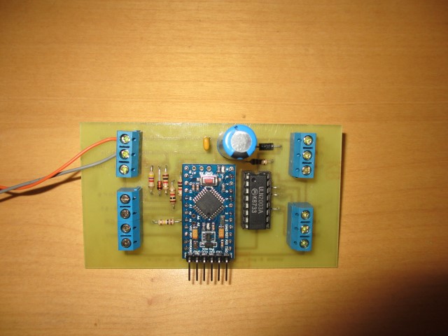
Photo 2
Loss of voltage in control board.
To prevent damage from connecting the battery the wrong way, the supply to the whole system is fed through a diode. This loses 0.6v. It could be replaced by a relay, but this would be more complicated, more expensive, and less reliable.
The outputs from the Arduino are amplified by a ULN2003 Darlington driver, this loses another 0.8v. It could have been replaced by logic level FETs, or even relays (wash your mouth out!) but it is a very neat package, and standard with the control board for the semaphores. Thus with a 12.5 volt battery we have 11.1 volts available to drive the LEDs. With a battery down at 10.5v (we don’t want to go any lower, it damages the battery) we have 9.1v
Characteristics of LEDs
The voltage drop across an LED does change with current, but not like a resistor. For our purposes it can be approximated by a fixed voltage drop in series with a small resistor. At full current, the voltage drop for a single LED is ~2.1v for the red and yellow, and ~3.4v for the green. When working out the series resistors, measure the forward voltage at the operating current.
If LEDs are used in parallel they should have some external load resistance to ensure they share the current.
Cluster LEDs Mk1
As the green and yellow cluster LEDs used on the swing link signal had been reasonably successful, our first attempt for this new signal was using MR11 1 watt clusters. The red and green were fine even with a low battery, but the yellow was noticeably less bright and when the input voltage went down it died completely. It is not known why these greens were OK and the yellow were not. Current consumption on 12v was red 49 mA, yellow 12.4 mA, green 32 mA
These clusters have a 120 degree beam angle, so are easy to see from the side. This is not all that useful, as it means that the visibility is lower for a given total light output than it would be for a more focussed beam. For a better description of this see John Lopez article in ME 2009. Once fitted with a hood, a lot of this light spread is cut off, and so wasted.
Cluster LEDs Mk2
We next tried clusters of white LEDs, the idea being to use pieces of floodlight filter material to get red/yellow/green. These appear to be 10 individual units, each having 3 LEDs built in. The filter material takes out a lot of light from the red and green, the yellow is ok down to about 10v, 11.4v at the battery. It does seem a shame to make white light (which isn’t easy with LEDs) and then filter 2/3 of it out. On 12v these units take 84 mA.
Array of 4 individual LEDs Mk3
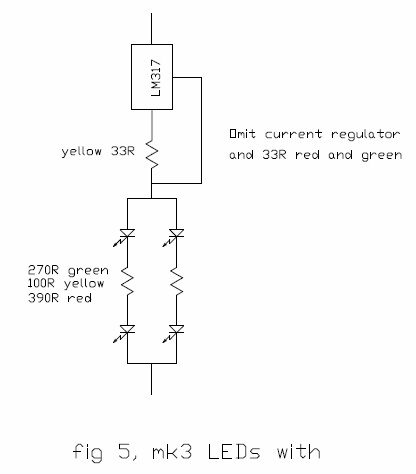
The swing link signal showed that we didn’t need 6 LEDs, so I bought some more high brightness individual LEDs (ref1) and arranged them in 2 lots of 2-in-series. When driven with the full 40mA, the red and green were blinding, but the yellow was noticeably less bright, this effect being more pronounced as the voltage dropped. What I have finished up with on yellow is a constant current source and a lower series resistor in each leg as shown in fig 5. This takes the full 40mA independent of supply voltage (until the battery is well below 10v), and the current sense resistors on red have been adjusted to give 10 mA, giving the same perceived brightness as yellow. This didn’t work on green, it appears the higher forward voltage drop doesn’t leave enough for operation of the regulator. I have set the series resistors on green so that at full battery voltage the current is 40mA, but have the Arduino output a variable mark/space signal dependant on battery voltage to keep a constant 10mA average current. How to work this out is given in the appendix (website). Next batch will have this on reds instead of current control for simplicity.
The LEDs have a beam angle of 30 degrees (15 degrees either side of centre). The prototype assembly is shown in photo 3. The rubber band is temporary, it’s a lot easier than 4 screws during development.
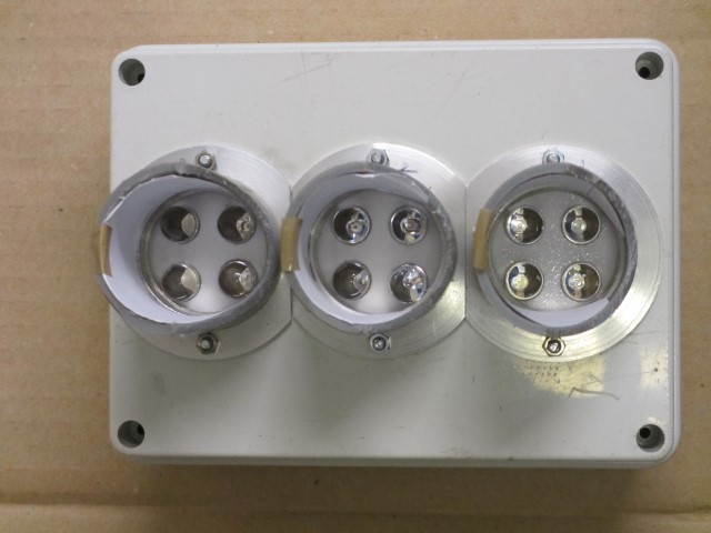
Photo 3
The only downside of this set up is that the light is quite directional. This doesn’t matter as you approach the signal, as being on rails constrains the beholder to be reasonably in line, but when you draw up close to the signal it can be difficult to see which one is lit up, even with the inside of the hood white. I’m told that full size signals have an auxiliary side-facing lens for exactly this reason. If this proves to be a real problem, a lower powered diffuse LED facing sideways can be incorporated. To be pedantic, this side facing LED should be yellow, as failure of a single side facing red would give the false impression that the signal had changed. However, yellow is not as easy to see, and LEDs are very reliable.
Array of 4 individual LEDs Mk4
We then found some LEDs advertised as ‘suitable for use in signals’ (ref2), I doubt they meant railway signals. These are actually 3 LEDs in series in one unit, so the forward voltage drop is ~6v red and yellow, ~9v green, so the constant current arrangement used in mk3 won’t work, again there is not enough spare voltage to drive the regulator. The yellow is more like a traffic light (amber) than mk3, and the output is still OK at 9v even on green, which I don’t fully understand (it might be that the mk1 clusters have a bridge rectifier built in, taking another 1.2 V out of the system). The complete array is shown in photo 4.
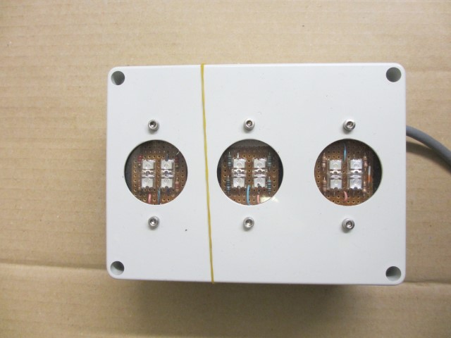
Photo 4
On full current the red and green are again brighter than needed, and the spread of light is a lot higher than mk3, so the inside of the hood is well lit up. The downside is that each unit takes 30mA, and there are 4 in parallel, 120mA total. If we eventually go down this route I will just accept the yellow getting slightly dimmer with reducing battery voltage, and use the pulse width modulation described above for red and green. Why not pwm the yellow you ask? If I set the series resistor to give full current at 9v, and then the Arduino has a glitch and stops the pwm with the output ‘on’, and a fully charged battery it could burn out the LEDs. I think this is unlikely, but I don’t know how unlikely.
Enclosure
The enclosure in photo 4 is a IP56 box from Newey and Eyre, part number NLPE30A. As is often the case, it is the most expensive single component by far, all of about £5. If we use the mk 3 or mk 4 LEDs it is tempting to buy boxes with transparent lids and mount the LEDs inside, less chance of water getting in. The hoods are pieces of 40mm plastic waste pipe press fitted onto aluminium flanges. In the prototype I used some grey pipe I had in stock (junk box), production units will be white. For mk1 or mk2, the aluminium flange should be arranged to hold the clusters in place and support the filter material. As the beam angle on mk3 is quite narrow the mounting to the signal post must allow for rotation to be adjusted to point down the track, and it works best to have the signal on the outside of a curve. I have a camera tripod on which I mount the box so it can be shuffled around for best position before concreting in the post.
An alternative answer to flat batteries
I then remembered that I have a 12v-24v step up converter which I bought to drive one of those ex radar blowers to use as a steam raiser. It wasn’t powerful enough to run a motor, but it’s plenty powerful enough for these LEDs. It can be set to give 13.4v output (ie 12v at the LEDs) with any input voltage above about 5v, it’s efficiency is about 60% with a 10v input, better with higher input volts. This might make mk1 or mk 2 viable, but is not necessary with mk3 or 4.
Which one is best?
We’ve decided to make a trial batch of mk3. As the LED units are interchangeable, this is not irrevocable. As we have already got one set of mk4s we will use them as well. If you’ve got mains power I’d go for reds and greens from mk1 and the yellow from mk2. It’s a lot easier than making up the mk3 and 4 versions, and current consumption isn’t an issue. If you want to see them in action pay us a visit in Warrington.
Next step
With all the hype from the green lobby about renewable energy we’ve bought a solar panel. If this works out we will have solved the flat battery problem. However a trial installation in December, pointing straight at the noon day sun (OK it was overcast), produced very little output. Watch this space, if it works I’ll do a write up. Someone out there must have built a windmill, all those I can find on the web are too big. I know you can buy them for caravans and boats, but they are not cheap. Otherwise I quite fancy a generator waggon. The big loco chaps can drag it round each running day and charge up the spare battery. Call it a dynamic test vehicle and they’ll be queuing up.
Sooner or later the property developer next to our track will build houses, and we will then try to get a mains supply laid on.
References
1. 10mm diameter, 30 degree viewing angle, at 20mA red = 8000mcd, yellow = 5000mcd, green = 12000 mcd, obtained from fusion_online via ebay
2. TruOpto OSR5M3Z4E1P red, OSY5M3Z4E1P yellow, OSG5M3Z4E1P green