
DEVIATION REPORT: ISSUE 3, March 2021
DEVIATION REPORT: ISSUE 3, MARCH 2021
All photos of this project can be found in The Deviation Gallery Winter 2020
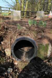
Both pillars in the ditch have been built to a height of 3 breeze blocks with soil from the ditch firmed around them. The ditch crossing photo shows the wide area of firm ground for walking across the tubes while some landscaping has been applied above the entrance by planting daffodils.
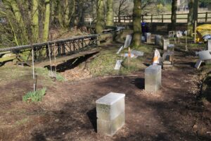
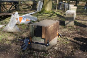
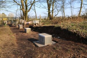
Of the seventeen pillars which can be built before the track is broken into (implementation) sixteen have had their base flag laid with the first block aligned and grouted in place with six of them built up to the correct height according to the relevant gradient. The fixing of the top block onto a pillar to get the exact height is something of an art form requiring juggling solid blocks of differing thicknesses then grouted to varying depths. When there are no suitable blocks a shuttering former has been constructed to an ingenious design which slips over the tower then is tightened so that the top edge is at the correct height before pouring in concrete. It is easily loosened for removal once the concrete has set – see the photo of it in action on pillar 499 bringing it up level with the preceding pillar 498.
While the cutting was easy to dig into it took many days of hard graft to remove and spread the soil. It was found that the exposed ground was soft and rather spongy so the pillar in the centre has had larger stone inserted underneath its base slab. A drainage channel is to be constructed down the side but the ground may well become firm once the soil dries out and the water table lowers. The track cutting through the resulting mound makes a small but attractive feature.
Whilst digging out the ground for the bases by two large trees our worse fears were confirmed – large tree roots below the surface which had to be hacked out. The policy from now on is to set the top of the pillar lower than it should be and insert an extra red plastic packer (5.6mm) under the beam to bring it back up to its proper height. As the pillar rises/tilts the plastic packer can be replaced by smaller ones with any tilt being handled by one side of the beam having a different sized packer inserted than the other.
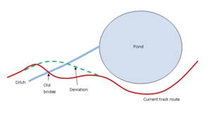
While calculating the gradient for the drop in height (79mm) from the level beam 499 to the extension at beam 512 it was found the pillar 512 has been lifted by the nearby tree roots. With beam 512 too high it throws the height calculations on the other pillars and hence the gradient profile coming down from the summit. In addition the running track is plunging down steeper towards the pond on beam 513. Pillar 512 will now be demolished and its base realigned when the deviation is joined up so that beam 513 will point at a better angle towards the deviation.
 A marathon session by Paul saw 14 beams welded. up in one go. There are 11 beams for the deviation consisting of a 2 meter beam of 102mm x 51mm channel the larger depth allowing it to abut up to the 3 meter beam, 8 normal 2 meter beams and the fiddle beam of 630mm. Extra steel had been ordered to construct three 6 foot beams. The beams have been galvanised and straightened, ready for test fitting and future installation.
The Deviation Project has left the club a legacy in the form of a jig that can construct both 2 meter and 6 foot metal beams enabling the deteriorating concrete beams on the main circuit be replaced.
Dave Mulholland and Craig Scarisbrick