
DEVIATION REPORT: ISSUE 2, DECEMBER 2020
DEVIATION REPORT: ISSUE 2, DECEMBER 2020
All photos of this project can be found in The Deviation Gallery Winter 2020
Enough materials have been bought to enable the bases to be laid for seventeen pillars and for these to be built up initially to the height of two breeze blocks. The remaining five pillars can only be erected during implementation and will be resourced later. There is a limit as to how many 600 x 600mm concrete flags or 215mm hollow dense concrete blocks can be carried in a car.
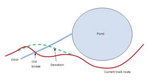
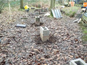
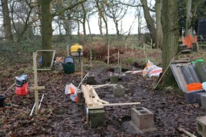 The radii of the curve from beam 076 through to the the pillar on the other side of the ditch had a final check by laying the curve plotting tool against the wooded sticks spaced at 2020mm marking the position of the centre of the pillars. When digging out the square for a base flag the stick has to be removed. Another complication was that we were starting to build pillars on a 60ft radius curve. To mirror the curve three reference points were inserted in the ground adjacent to three sticks using a wooden “alignment offset frame”. The frame laid against two of the reference points at a time gave the exact position, at the end of its legs, of the centre of the flag. The stick could then be removed and a square dug to lay a 600 x 600 base flag on sharp sand. The first pillar block laid on the flag was adjusted to the correct angle with the curve plotting tool. Five of the six pillars before the ditch have been built to the height of two 215mm blocks.
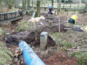
 The bank had already been dug away and the floor of the ditch levelled for the first of the two pillars to support the beam crossing over the pipe. This beam is on a 70ft radius and skewed at 45 degrees. The base was shuttered and the concrete mixer brought to the edge of the ditch to enable a couple of mixes to be poured down to form a solid base. The top surface was smoothed to provide a level base for the first block of the pillar. Its correct position was achieved using a combination of a vertical laser beam, a 2020 white pipe for the correct length and a plum line for the centre of the block. This pillar is now three blocks high with at least one more block to be added to bring it up-to almost rail height. The bank on the other side of the pipe has been dug out and the floor shuttered ready to lay the concrete base for the second pillar.
 Four of the 6ft heavy concrete beams from the old curve were removed using the four man lifting bars and stacked neatly with the others against the fence. The pillars are very strong and resist being broken up even with the large sledge hammer. The rubble from the first one is now down in the ditch.
All of the steel has been cut to length for the construction of the 3 meter beam and the nine 2 meter standard beams for the deviation together with the 6 foot lengths to make replacement beams for the existing track. The angle iron and flat bar cross members have also been cut and their holes drilled. The 3 meter beam (to bridge the tree roots) and the preceding 2 meter beam have both been welded up using 102mm x 51mm channel.
Dave Mulholland and Craig Scarisbrick