
Trackside Report – Daresbury Gazette Xtra
Daresbury Gazette Xtra!
Latest trackside news bulletins from Daresbury and the WDMES
<< Back to the Daresbury Gazette…
DEVIATION IMPLEMENTATION REPORT: ISSUE 4, DECEMBER 2021
All photos of this project can be found in The Deviation Completion Gallery 2021
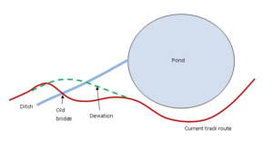
Reasons for building the Deviation
The main purpose of the Deviation construction work is to:-
- Bypass a reverse curve containing a tight 35ft radius curve which has resulted in a history of accidents and a high rate of track wear and maintenance issues.
- Avoid the old metal bridge with a collapsing foundation leading to the likelihood of the bridge’s failure.
- Build new track pillars and improved track alignment on steel beams to provide long term solution to avoid tree roots pushing over the track.
 The original route via the old bridge has deteriorated due to a combination of reasons culminating in a situation where track maintenance cannot be controlled to an adequate level. This was becoming a losing battle against nature and the deterioration of the track structures. Considering the future for the operation of the track, much careful consideration and discussion took place for providing the best all-round solution. The work on the Deviation is a long term investment in the club’s track to achieve low maintenance, improve safety and to reinstate full maintenance control.
Deviation Pre-parity Work
During the summer part of the deviation was built with seventeen of the twenty three pillars constructed and eight of the twenty four metal beams laid including the rail.
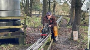
Following on from a very successful night running session on Friday 08th October the track was broken into the next day to commence the work of joining up the deviation from the main track to the extension. It was important that enough manpower capable of lifting nine heavy cast concrete beams could be brought together on that weekend.
 Firstly the jumper leads across the rail joints were unscrewed, these complete the track circuit for the signals. There is lot more work involved in installing automatic colour light signalling than the majority realise. The metal anti-tip rail as far as the old bridge was dismantled and put into store. Wooden anti-tip rail beyond the bridge was removed.
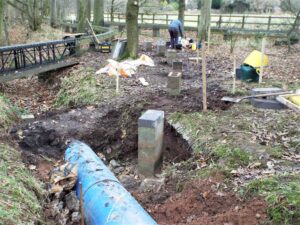
The nine 6ft concrete beams were lifted and moved to near the plastic water tower. The track was cut in sections so that each beam could be lifted onto the works truck brought right up to each join and then rolled down the remaining track to the store. Five of the pillars were knocked down to clear ground for the realignment of the track. Although they were over 50 years old the pillars resisted the sledge hammer and could not be broken up until their solid base of concrete was dug out. At a later date the rubble will be moved to cover another blue plastic pipe to be laid in the ditch
Pillar 078 at the apex of the sharp left hand curve of the reverse curve was close to the trunk of a large tree. On demolition of this pillar it became clear why the curve could no longer be maintained as the tree itself was leaning against the pillar and gradually pushing it over altering the radius and cant of the curve.
After the metal bridge fourteen 2 meter metal beams 501 to 514 on the extension were lifted and used on the deviation. The 5 inch rail being in good condition was put into store while the 3 ½ inch rail was recycled as the 3 ½ inch on the deviation. The sleepers have
been re-used by turning them over so that new holes could be drilled into a flat surface.
Construction Work at the end of the Main Track
 Between the existing track and the section of deviation already built four holes were dug/enlarged for new pillar flags laid on grit sand with 3 x 2 flags underneath the heavier 3 meter metal beam against the normal 2 x 2 flag for the 2 meter beams. A six foot lintel beam in good condition was retrieved and rolled down the old track to replace beam 276. Four new pillars were built to height plus the top face of one pillar 489 adjusted to install one of the three six foot metal beams in stock to replace the lintel beam. Two pillars had step changes built into their top surface to accommodate the deeper steel section required to strengthen the longer 3 meter beam. One 2 meter beam also has the deeper section.
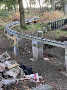
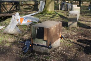
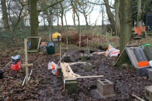
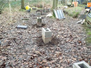
It takes three sessions to build a pillar. The positioning of the first breeze block on the base flag is critical using a 2020mm white pole for the distance between the blocks and the curve plotting tool for the correct curvature (90, 70 or 60ft radius). A second breeze block is then added and allowed to set. Only then can the remaining height of the top block be calculated including an allowance for the gradient. Blocks of varying thickness are cut to size and the number of grouts added. If the top block is thin i.e. less than 50mm it may crack when drilled so the pillar is shuttered with a wooden box and concrete poured in.
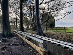
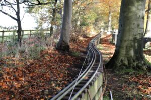
Five beams were laid as follows:- a new thick walled 2 meter beam, the 3 meter beam spanning the tree roots, then three standard 2 meter beams lifted from the extension.
There is a slight left curve then a straight past the tree followed by two transition beams curving to the right positioning the track to join up with the beams already laid on a 60ft radius curve. On the deviation there are six beams on a reducing uphill gradient averaging 1:224 then six level beams while the old track had a constant rise of 1:159 on nine beams before humping over the old bridge. The deviation is two inches lower crossing the ditch.
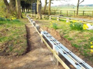
Laying Track on Steel Beams
 The track is laid on steel beams as follows. Key sleepers are first bolted to four cross pieces welded across the beam. The rail is bent to the appropriate curve (90, 70 or 60ft radius) using the curve bending tool. The adjustment using the tightening screw is very fine and can easily result in too much or too little curve in the rail. Once the correct setting has been found then all the required rails are bent and laid out on the key sleepers.
The outer rail is always laid first as it has the furthest to travel round a curve. Tiny metal nails are used on each side of the rail to hold it onto the four key sleepers bolted onto each beam. The pre-curved rail is initially tied down to the first and third key sleeper. It is then checked by eye before knocking in the nails on the second and fourth sleeper. After any further adjustment the outer rail is then screwed down. The inside rail is added using the track spacers and shortened so that the two joints are opposite one another to achieve a clickerty-clack from the wheels of the trucks. The 3½ inch rail is positioned. The rest of the sleepers are then laid out and all the rails screwed down in one mammoth session.
Each steel beam has a 5mm blue plastic packer inserted underneath its end to provide a smooth surface and also to make sure that a sloping beam does not catch the edge of the flat pillar top. When laying or altering track if there is a tree nearby whose roots could lift a pillar then its height is now built 12mm lower than required. On fixing down the steel beam an additional two 6mm red packers are added to the blue packer to bring the beam back up to its correct height. The idea is that as the tree roots lift/tilt the pillar the track can be brought back level by changing the red packers to packers of lesser thickness.
Construction Work joining the Extension
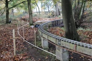
 To join the deviation to the extension the right hand curve to the left of the water tank from pillars 513 to 517 had to be readjusted (nudged). The 2 x 2 base flags were exposed unfortunately cutting the signal cables in four places. The proceeding pillars 511 and 512 had to be demolished and rebuilt as they were too far over to the right on a tighter curve.
The curve was reset by working backwards from pillar 517 towards pillar 511. Nudging of the base flag of the pillars with crow bars had to be undertaken a number of times to gradually realign the pillars with the resulting curve continually checked with the curve plotting tool. The curve is now at a maximum of 90ft radius on two beams as against originally at 70ft on three beams. The 630mm long fiddle beam 510 adjusted any change in the beam spacing caused by the realignment of the curve. The down gradient to the extension at 1:250 is less steep and shorter than it was from the old bridge at1:212. Wooden anti-tip rail planks were attached to the pillars with new tantalised 3 x 2 blocks.
The cant was set on the curves by adding an extra packer on top of the blue packer on one side only tilting the beam over to the appropriate degree of cant. Transition beams are used at both ends. The degree of cant is checked with a home made metal swingometer.
The signals were brought back into operation by drilling the 5inch rail either side of each fish-plate then attaching stainless steel jumpers to bridge the gap to retain continuity.
The signal cable feeds to the track were relayed under the beams and joined to the rail.
Maintenance Work
With the track closed and manpower available the opportunity was taken to work on four outstanding maintenance issues on the main track.
- Replaced deteriorating concrete lintel beam 276 with one from the deviation. NOTE that the 6ft concrete beams round the old track are starting to break up with three already replaced and two more experimental shuttered. Only two 6ft steel beams in stock. The jig to construct new ones is in the container.
- On the RHS long straight four beams 055 to 058 being tilted by trees were lifted. The top surface of the three leaning pillars were cleaned and levelled using the whizzer while the pillar next to the tree was reduced in height by12mm. The original beams were reset with their heights adjusted back to level using plastic packers.
- On the down line near the water tank beams 145 & 146 were realigned by jacking them up and then levelled on pillar 145 using packers under the two beams.
- By the station pillar 014 had been shifted 2 inches to the right by a tree. The pillar was cut down and rebuilt on a 2 x 2 flag laid on sand. Crumbling beams 014 & 015 were replaced by the last two concrete beams with packers to bring back to height..
Proposal for a Steam-fair Station
Running away from the level summit at the ditch heading towards the water tank there are five suitable straight beams on a shallow down gradient. The suggestion is that this area should be considered to see if it is feasible and if there is enough support to build a station to load passengers at the steam-fair through a gate in the fence. The station would be near to the viewing area with the big advantage of loaded trains starting downhill.
Dave Mulholland and Craig Scarisbrick
DEVIATION REPORT: ISSUE 3, MARCH 2021
All photos of this project can be found in The Deviation Gallery Winter 2020
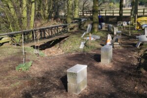
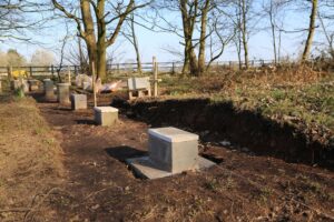
Both pillars in the ditch have been built to a height of 3 breeze blocks with soil from the ditch firmed around them. The ditch crossing photo shows the wide area of firm ground for walking across the tubes while some landscaping has been applied above the entrance by planting daffodils.
Of the seventeen pillars which can be built before the track is broken into (implementation) sixteen have had their base flag laid with the first block aligned and grouted in place with six of them built up to the correct height according to the relevant gradient. The fixing of the top block onto a pillar to get the exact height is something of an art form requiring juggling solid blocks of differing thicknesses then grouted to varying depths. When there are no suitable blocks a shuttering former has been constructed to an ingenious design which slips over the tower then is tightened so that the top edge is at the correct height before pouring in concrete. It is easily loosened for removal once the concrete has set – see the photo of it in action on pillar 499 bringing it up level with the preceding pillar 498.
While the cutting was easy to dig into it took many days of hard graft to remove and spread the soil. It was found that the exposed ground was soft and rather spongy so the pillar in the centre has had larger stone inserted underneath its base slab. A drainage channel is to be constructed down the side but the ground may well become firm once the soil dries out and the water table lowers. The track cutting through the resulting mound makes a small but attractive feature.
Whilst digging out the ground for the bases by two large trees our worse fears were confirmed – large tree roots below the surface which had to be hacked out. The policy from now on is to set the top of the pillar lower than it should be and insert an extra red plastic packer (5.6mm) under the beam to bring it back up to its proper height. As the pillar rises/tilts the plastic packer can be replaced by smaller ones with any tilt being handled by one side of the beam having a different sized packer inserted than the other.
While calculating the gradient for the drop in height (79mm) from the level beam 499 to the extension at beam 512 it was found the pillar 512 has been lifted by the nearby tree roots. With beam 512 too high it throws the height calculations on the other pillars and hence the gradient profile coming down from the summit. In addition the running track is plunging down steeper towards the pond on beam 513. Pillar 512 will now be demolished and its base realigned when the deviation is joined up so that beam 513 will point at a better angle towards the deviation.
 A marathon session by Paul saw 14 beams welded. up in one go. There are 11 beams for the deviation consisting of a 2 meter beam of 102mm x 51mm channel the larger depth allowing it to abut up to the 3 meter beam, 8 normal 2 meter beams and the fiddle beam of 630mm. Extra steel had been ordered to construct three 6 foot beams. The beams have been galvanised and straightened, ready for test fitting and future installation.
The Deviation Project has left the club a legacy in the form of a jig that can construct both 2 meter and 6 foot metal beams enabling the deteriorating concrete beams on the main circuit be replaced.
Dave Mulholland and Craig Scarisbrick
DEVIATION REPORT: ISSUE 2, DECEMBER 2020
All photos of this project can be found in The Deviation Gallery Winter 2020
Enough materials have been bought to enable the bases to be laid for seventeen pillars and for these to be built up initially to the height of two breeze blocks. The remaining five pillars can only be erected during implementation and will be resourced later. There is a limit as to how many 600 x 600mm concrete flags or 215mm hollow dense concrete blocks can be carried in a car.
 The radii of the curve from beam 076 through to the the pillar on the other side of the ditch had a final check by laying the curve plotting tool against the wooded sticks spaced at 2020mm marking the position of the centre of the pillars. When digging out the square for a base flag the stick has to be removed. Another complication was that we were starting to build pillars on a 60ft radius curve. To mirror the curve three reference points were inserted in the ground adjacent to three sticks using a wooden “alignment offset frame”. The frame laid against two of the reference points at a time gave the exact position, at the end of its legs, of the centre of the flag. The stick could then be removed and a square dug to lay a 600 x 600 base flag on sharp sand. The first pillar block laid on the flag was adjusted to the correct angle with the curve plotting tool. Five of the six pillars before the ditch have been built to the height of two 215mm blocks.
 The bank had already been dug away and the floor of the ditch levelled for the first of the two pillars to support the beam crossing over the pipe. This beam is on a 70ft radius and skewed at 45 degrees. The base was shuttered and the concrete mixer brought to the edge of the ditch to enable a couple of mixes to be poured down to form a solid base. The top surface was smoothed to provide a level base for the first block of the pillar. Its correct position was achieved using a combination of a vertical laser beam, a 2020 white pipe for the correct length and a plum line for the centre of the block. This pillar is now three blocks high with at least one more block to be added to bring it up-to almost rail height. The bank on the other side of the pipe has been dug out and the floor shuttered ready to lay the concrete base for the second pillar.
 Four of the 6ft heavy concrete beams from the old curve were removed using the four man lifting bars and stacked neatly with the others against the fence. The pillars are very strong and resist being broken up even with the large sledge hammer. The rubble from the first one is now down in the ditch.
All of the steel has been cut to length for the construction of the 3 meter beam and the nine 2 meter standard beams for the deviation together with the 6 foot lengths to make replacement beams for the existing track. The angle iron and flat bar cross members have also been cut and their holes drilled. The 3 meter beam (to bridge the tree roots) and the preceding 2 meter beam have both been welded up using 102mm x 51mm channel.
Dave Mulholland and Craig Scarisbrick
DEVIATION REPORT: ISSUE 1, OCTOBER 2020
All photos of this project can be found in The Deviation Gallery Winter 2020
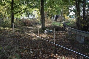
The Deviation starts at beam 076 with a straight section which includes a 3 meter metal beam spanning the tree roots c urrently lifting beam 078 and then bends away to the right on curves up to 60ft in radius. The ditch is crossed 6 meters to the left of the metal bridge then continues in a straight line until joining the extension at beam 513 via a slight curve. The new route eliminates the reverse curve, bypasses the sharp right hand curve and solves any problems caused by the deteriorating state of the old bridge. The rails are on 23 metal beams giving a total length of 46.5 meters with a fall of only 40mm i.e. level track.
 Initial ground work involved inserting 6 posts along the route using a laser beam to set cross pieces at rail height. Calculations show that the ground either side of the ditch needs digging out to form a shallow cutting. Before the ditch only a small amount of digging is required while the other side is higher with a greater spread.
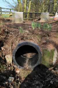
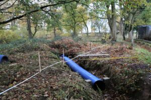
Four 1.4 meter long thick walled water pipes 560mm in diameter were obtained free of charge and off-loaded by the station. They were moved up to the ditch by inserting a metal bar through the tube and with a four man lift placing each across two of the small passenger trucks to form a bogie train. After some scratching of heads on how to unload them the solution was to hold tight to the trucks and give the pipe a quick push keeping well out of the way as they rolled themselves to their resting place.
 The ground surrounding the ditch has been cleared using a brush cutter and the bottom of the ditch levelled. The first water pipe was pushed over the edge and easily rolled into position within the ditch. The second pipe was not quite aligned properly starting its roll. It bounced up the bank on the far side before dropping back to fit perfectly with its end hard against the end of the first pipe – obviously somebody knew what they were doing. Stone left over from the drainage channels at the entrance gate has been used to pack round the bottom of the pipes and by rocking the pipes back and forth settle some stone underneath. A start has been made to drop rubble down the sides of the pipes initially taken from by the water tank helping to tidy up that area.
A viable route has been successfully plotted. Marking out is undertaken using an adjustable curve plotting tool with the appropriate radius (straight, 90ft, 70ft, 60ft) set for the curves together with a 2020mm white pipe to set the distance. The tool is laid against two previously inserted posts with the next post, at the end of the tool, being the position of a pillar for the 2 meter metal beam.
The route starts with a 7 meter straight section which cuts through the reverse curve followed by two transition curves set at 90ft then 70ft leading into the 60ft radius curves. The ditch is crossed on a 70ft radius curve with a skew of 45 degrees, the two pillars located either side of the ditch are on unstable ground. Nine beams take the track through the middle of two trees in a straight line before joining the extension.
The steel to construct the extra eleven beams required for the deviation has been ordered. Money was authorised to increase the steel order to include the fabrication of a 6 foot jig plus the construction of 2/3 beams. One of these 6 foot metal beams has already been allocated to replace beam 212 on the down line opposite the station which is breaking up. The 6 foot jig is a lasting legacy to the club which will be used in the future
Dave Mulholland and Craig Scarisbrick
Model Engineer spotted with N Gauge!
Mini TRACKSIDE REPORT: Model Engineer spotted with N Gauge!
Special news report just in…
Barrie paid a rare visit to the TGMRC (whilst preparations being made for an up and coming exhibition) and to our shock and disbelief he was spotted ‘rerailing’ a train that was N Gauge! We never thought this day would come – could this mean his famous steaming bay is soon up for grabs at Daresbury? Will he be creating his own N Gauge layout? Fear not, 5 inch Gauge Steam engines are within his DNA!
The Mysterious ‘Who painted the tunnel black!?’
TRACKSIDE REPORT: The Mysterious ‘Who painted the tunnel black!?’
Special news report just in…
Steve Hudson and his lovely wife Christine whilst messing about in the woods, stumbled across a ‘bespectacled character’ covered in black spots!! Not something you would expect with love in the air! It was infact our Chairman Barry Linaker who had been painting the tunnel black! It is now akin to the Black hole of Calcutta. A nice surprise for those that turned up on Easter Sunday for track running!
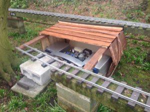
Storm Gareth Attacks Track Cleaner and Shed!
TRACKSIDE REPORT: Storm Gareth Attacks Track Cleaner and Shed!
Special news report just in…
Storm Gareth has been a bit too windy recently, and has managed to blow over the track cleaner, taking its shed and some of the track and support pillar with it from the siding! Luckily it was repaired and the track cleaner is back safe in its home, ready to clean the track again for another day!
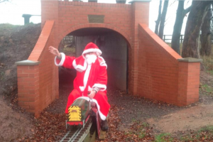
Santa visits Tunnel via the club loco!
TRACKSIDE REPORT: Santa spotted at Daresbury Track at the new Tunnel!
Special news report just in…
Santa has decided to drop in at the Daresbury Track on Sunday 23rd December 2018 before his busy evening of Christmas Eve and Christmas Day! Hopefully a quick ride around the track (in the opposite direction!) will give him some great ideas to deliver his presents!
Could the Club Black 5 have been spotted!?
TRACKSIDE REPORT: Rumour has it a Steam Club Loco is spotted at Daresbury Track
Special news report just in…
Speculation at the track since the last known ‘where-a-bouts’ in June is that the Club Black 5 Locomotive made an appearance at Night Run 6 – photos of the said loco may have been captured within the following gallery…